Agricultural Sprayer Boom Height Control
This isn’t a fancy or particularly exotic control system example. I share it here because it sat in an old notebook as an example of fun modelling process. It involved two simple single-input, single-output (SISO) control loops with the dynamics of actuating one side coupled-through to the other via an uncontrolled, unobserved axis.
I remember struggling to reduce the model. When I put the, “uncontrolled” axis dynamics central to the model and treated my axes of interest as rate inputs I had a moment of joy over the elegant simplicity of it. This a great example of the joy of the modelling process: struggling with equations and signal flows until the, “aha!” moment.
A model that fairly covers the basic dynamics of a system is useful for testing controller concepts in principle at the desk. For example individual non-linearities can be simulated and pondered.
An actual, “plant” (agricultural sprayer in this case) throws all the dynamics and non-linearities at you simultaneously, making controller design iteration challenging on even the simplest of plants.
If you can get a basic model simulating at your bench you can layer-on non-linearities and parameter estimates to gain insight towards live tuning.
Background
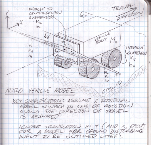
Self-propelled agricultural sprayers consist of a heavy vehicle and a, “boom” that unfolds to lengths exceeding 50 feet on each side. Total spray swath widths can exceed 100 feet.
As the vehicle moves over a field an operator controls the boom center section height as well as the left and right tip height by means of hydraulic controls in the cab. Height sensor feedback and hydraulic valve control electronics can automate this process.
The center section is moved up and down relative to the chassis for nominal height control. The left and right height control is rotational relative to the center section to which the left and right booms are pinned. This controls the boom tip height over ground or crop.
Boom Dynamics and Control
Boom height control automation is not new. Wheel sensors tracking the ground work in some cases for feedback to hydraulic valve controllers. For a couple decades it’s been enabled by down-facing ultrasonic sensors. These product configurations are available across brands and after-market suppliers for retrofit on many sprayer models. Norac was an early market provider. For ultrasonic solutions. This short document provides a decent overview that matches my general assessment of available technology and techniques.
Available solutions are limited by the inherent lag in a down-facing sensor as feedback to a low bandwidth mechanical structure. This is a problem at typical spray vehicle speeds exceeding 10 miles per hour across a field.
The problem is akin to driving a curvy road in your car with your head out the window looking straight down at the centerline of the road. Please do not attempt this trick! You can imagine how difficult it would be to stay in your lane at even moderate speed.
System Model
Some years ago I worked in this area. I was dissatisfied with uncontrollable dynamics of the moving spray rig. My solution space was limited for commercial reasons. I was curious to develop a more complete system model to aid in understanding how to account for the coupling of controlled-axes to uncontrolled axes.
Vehicle Model
The following sketch illustrates the primary elements of a self-propelled sprayer
- High Mass vehicle (including tank).
- Relatively lower mass right and left booms pinned and actuated in rotation against a…
- Center section with a vertical axis of motion relative to the body which also…
- Rotates some degrees about the along-path centerline but is…
- Self-levelling relative to the body by way of springs.
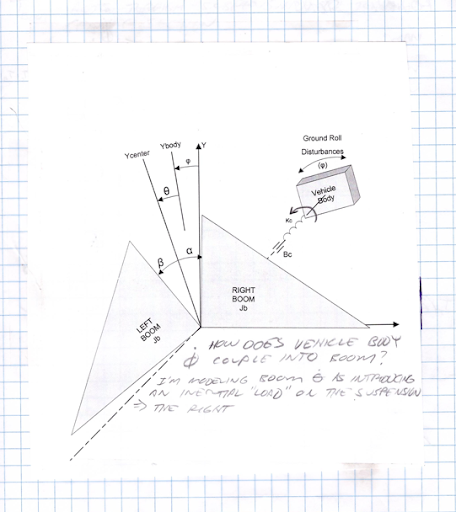
System Block Diagram
The sketch above simplifies-down to a free body diagram…
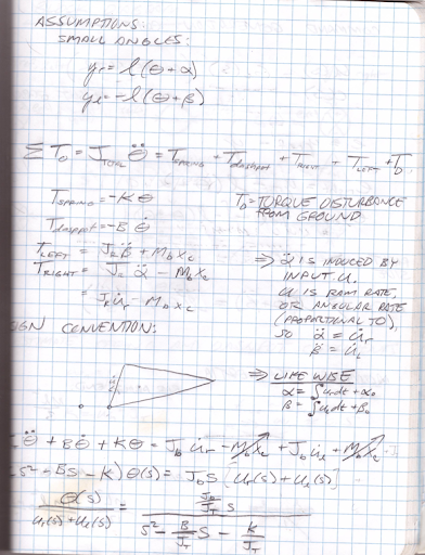
Equations of Motion
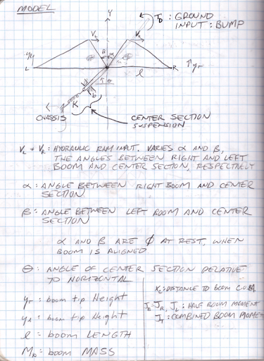
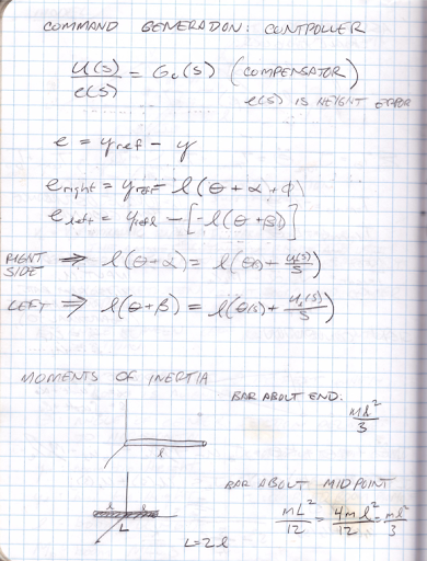
Relevant variable descriptions and equations of motion follow in these notes. The main point of the model is that the uncontrolled center section rotational model is actually the, “plant”. The control axes are the left and right boom angles relative to this center section.
The center section is coupled through a torsional spring to the vehicle body. The body is subject to ground disturbances. Therefore the center section is subject to torsional disturbances from a rocking vehicle that rolls over ground. It is also torqued in reaction to the left and right boom hydraulic cylinders as they actuate the side booms relative to this center section.
The model assumes there is no control over this center-section rotational axis. The center section can be actuated up and down but this is not relevant to the problem of exiting the center rotational axis from vehicle disturbances or as a reaction to side boom height control.
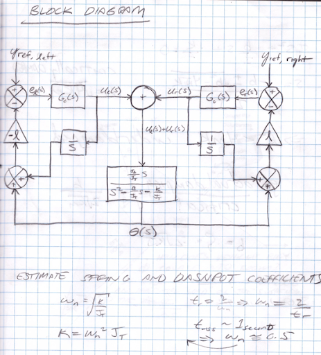
Plant and Compensator Block Diagram
The problem simplifies-down to the center-section rotational plant at the center of the sketch below. The left- and right-boom control outputs are rates which integrate and operate over boom lengths ‘l’ to control boom tip height. The top-center summing junction represents the boom drive coupling into the center section.
Matlab and Simulink Simulations
The script runboomsim.m initializes variables, runs simulink model boomsim.slx, and plots results. The Simulink diagram is shown here.
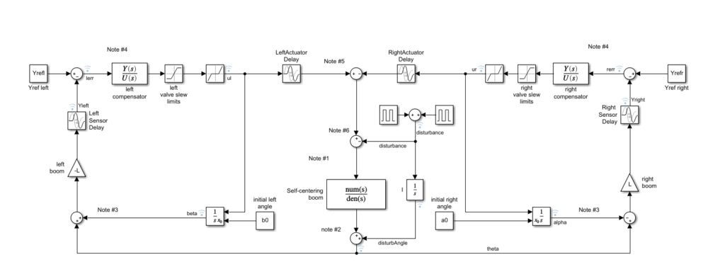
Simulation details
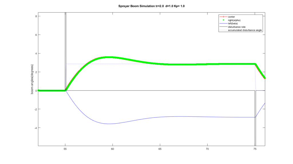
The command outputs are rates: rate-of-flow of hydraulic fluid drives the cylinders. This slews the left- and right-boom angles with respect to the center section. The sample plot here shows a short disturbance, “rate” pulse. You can think of this disturbance as the wheels of one side of the vehicle rising on a short ramp to a new level that produces a roll angle.
Each rate pulse, “up” is like a rise to roll along the humps in the sketch below. A rate pulse, “down” is like a return to the flat.
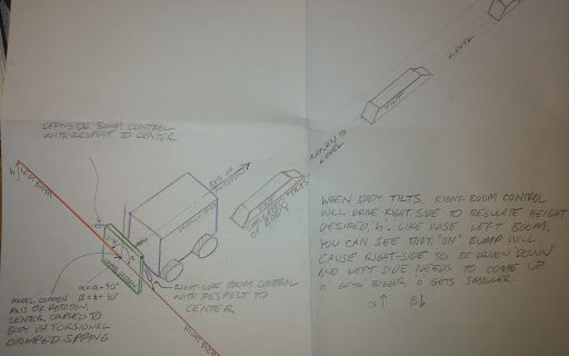
The resulting simulation signals plot as shown below. For the right- and left-boom tips to maintain a set-point height above ground you can see the right side (green) must drive with respect to the center by a few degrees positive angle. The left by a few degrees negative for this idealized, perfectly symmetrical test case. In this zoomed-out signals view you can still see the expected lag in right boom response to the disturbed center section. From this you can estimate a time constant for the simulated system if we were to zoom-in.
Simulation Disturbance accumulates to a constant roll angle
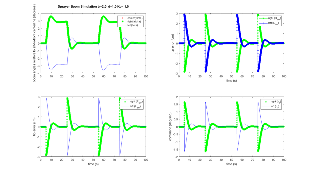
Boom Tip Height Regulation
The simulation regulates to zero for sake of simplicity, but you can imagine this would be some fraction of a meter over crop or ground.
Model Utility
The model presented above is useful for understanding the mechanics of an agricultural spray boom. Specifically, the coupling of the axes you might wish to control or are limited to control due to engineering or product constraints.
Extending the model
You can extend the model to account for non-linearities, particularly valve dead zones. Spool valves are the standard method for flow control in these applications. Undriven, the spool is centered with significant spool overlap. To actuate flow this overlap must be accounted for. This can be done through calibration and possibly continual identification techniques.
You then add this dead zone compensation to your positive or negative flow commands to jump the spool to the active region.
The model shared here is kept simple to illustrate the primary structure. From here you can enhance it with non-linearities and parameter refinements to suit a particular system you wish to simulate candidate control system designs.
Applying the Model in Other Domains
This model actuates two, “booms” mechanically grounded to a center-section object subject to disturbances. This includes the disturbance of having the booms actuated against it. One can think of unfolding and directing solar panels relative to a space station or capsule representing the, “center-section”. Therefore, this modelling technique appears generally applicable.
Simulating New Ideas
Recently Marketed Improvements
Some years between my brief time on this topic and this write-up Raven Technologies introduced chassis roll feed-forward and variable damping of the uncontrolled boom rotational axis. The video below describes this 2019 Raven innovation. These innovations appear sensible when I think back to fighting rotational excitation in this application.
If you watch the Raven video below you’ll see they’ve added and electro-chemical dashpot option to add an element of stiffness control to the center section that is natively sprung to the chassis.
My model above employs a fixed, specified damping ratio of d=1. Raven’s dynamic dashpot would enter the simulation relative to this term.
Chassis Roll Feed-Forward
Raven also describes a body-roll feed-forward scheme. You would model this by changing the simulated disturbance to feed-forward to the left- and right-boom servos before the roll disturbance acts on the center section. In my model above, the roll disturbance couples to the center section and the left- and right-booms servos simply react to it.
Topographical Data Feed-Forward
To my knowledge available commercial boom height control systems do not take advantage of topographical data. This can be available to the system by having driven through the field on previous narrower-width passes with GPS and inertial-sensor-equipped tractors (tillage, planting: neither of which would be as wide as a sprayer). Any GPS-guided tractor for planting or tillage has these data, so producing a crude topographical data set to use as feed-forward to boom height control is feasible.
For example, the sprayer may drive well left of a terrace that is known in topographical data. The right boom tip may strike this terrace if it relies solely on a tip height sensor to detect an abrupt rise at typical sprayer speeds. With topographical information, this right-boom rise can be predicted and, “fed forward” to the right boom.
Conclusion
A model need not be perfect or dimensionally accurate for it to be a useful basis for understanding dynamics, couplings, and non-linearities in a plant that needs a control system. Forcing myself to attempt a fair model before jumping to iterate schemes on live equipment has always helped me focus. It gives me a chance to strip away complexity, start simple, and build back complexity element-by-element only as needed.