Gyroscope History: Lead Computing Gunsights
In this post we’ll dissect and simulate basic concepts embodied in early gyro instrumentation applications in combat gun sights. We’ll build a deeper understanding of gyro mechanics through this application of their first principle: output torque resulting from precession. We’ll learn some interesting history too.
The basic problem to solve is this: when we fire a ballistic projectile how can the sight compensate to have the projectile intercept a moving target down range? We desire to hold the sight on the target and not guess how much to lead it by.
The British did early work in the Mk IID sight that was also produced in the US by the Sperry Gyroscope Company as the K-14 that saw use in US fighters during WWII. Charles Stark Draper started working in the same area in 1940 out of his Instrumentation lab at MIT.
Charles Stark Draper’s Gunsight Designs
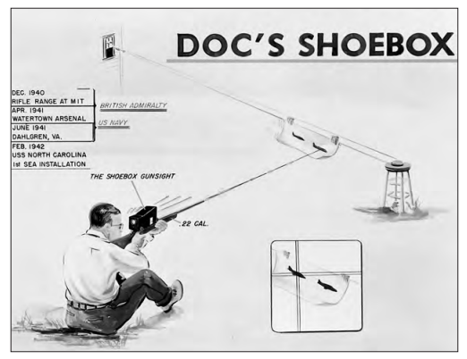
Draper’s first efforts in naval gunnery stemmed from a prototype he built in 1940 illustrated here. If some independent sensor could measure the crossing speed of the target paper, “Doc” is targeting and simultaneously know the line-of-sight of the barrel axis this independent actor could command the site in the “shoebox”.
The complicating factor is that the shoebox is the actor measuring the target crossing rate (drop rate too) by way of integrated gyroscopes. It is the, “computer” that assumes its own rates represent the target’s. This will present a problem we’ll cover below: tracking instability.
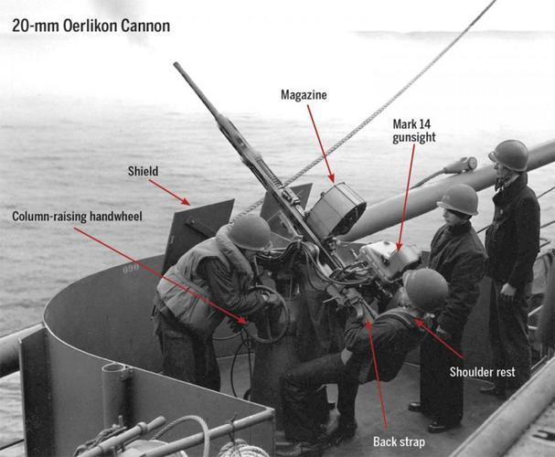
From this early, “shoe box” effort Draper designed anti-aircraft fire control systems for WWII ships. This became the Mark 14 sight manufactured by the Sperry Gyroscope Company. There’s some interesting information here.
John H. Blakelock’s, Automatic Control of Aircraft and Missiles, Second Edition Chapter 9 and Appendix J present Draper’s later work on the A-1 air-to-air sight. Blakelock writes on page 324 that Dr. Draper, “was probably the first person to completely understand the tracking instability phenomenon and was thus able to solve this troublesome problem”. This might be generous towards, “Doc” as he was called, given the amount of varied work in this field. Click the image below for book information.
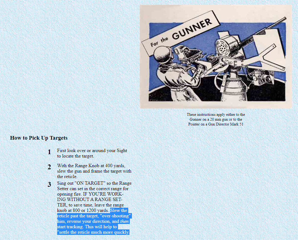
There’s a hint to this, “tracking instability” problem in training material for the Naval sight Mark 14 highlighted below. Our simulator will reveal why the Navy gave this advice. When a gunner increases slew rate of gun to catch-up to a target the pipper actually moves backwards in a manner that can confuse settling to smooth tracking. However, as you slow from ahead of a target this effect is less dramatic and easier to track to zero. We’ll make sense of this problem and identify how Draper and others mitigated the problem.
Draper’s A-1 Gunsight
Blakelock’s Appendix J introduces Draper’s later A-1 and A-4 air-to-air gun/rocket sight design. They were too late for WWII, but achieved some fame in the F86 Sabre vs. MIG battles over Korea in that later conflict.
The A-1 sight incorporated radar ranging. This eliminates the manual stadiametric ranging involving throttle grip twisting to close a concentric ring in the HUD on the wingspan of a target after having manually clicked the sight to specify target size. The promise of radar ranging eliminated this tedious process, but not without some growing pains as described in the article below, extracted from Air Power History (SUMMER 2009 – Volume 56, Number 2).
If you don’t read the entire article, scroll to the end and read the last paragraphs discussing the concepts of a, “heterogeneous engineer” and, “innovative departure”. These are relevant notions when attempting to gain traction when innovating in any industry or area.
Next Up…
With the above history a guide, the next post will present a simplified dynamic model we can use to investigate the, “tracking instability” problem in particular. There will be some matlab code to share so you’ll be able to play with the model yourself.