Quadrotor Build: Hardware, Software, and Tools
I’ve been making a book report out of the many interesting aspects revealed by a simple hobby drone. We’ve covered electro-mechanics of motors and propellers, fluid mechanics around propellers, simplified, “classical” single-input, single-output (SISO) axis control design and multi-input, and multi-output (MIMO) linear quadratic regulator (LQR) concepts to this point.
The background on the LQR gets down to the Calculus of Variations, solving the matrix Ricatti equation, and other topics that deserve many deep-dives, but if I go that path I might run out of air! It’s time to pull together a platform and a set of tools to use in proving our design ideas to date.
I have not yet covered a companion to the controller design: the state estimator. That’s going to be a Kalman filter that blends gyroscope, accelerometer, GPS, compass, and a barometer to estimate orientation and position of our platform. We’re going to circle back on this because I’m going to be starting with a flight controller that has a considerable amount of sensor and software support built-in. I’ll likely start with the state estimators available, and take these as feedback to code modifications I’ll make to implement the MIMO paper design.
It’s time to get a platform and a test stand up-and-running! We’ll prove some of our ideas, and chase new concepts as we go! Let’s Build!
Test System Requirements
The goal is to take paper designs and realize them in hardware, make adjustments to the designs based on testing, and observe our analytical approach results in flight. To do this we need hardware, software, and tools.
A former colleague of mine is a member of the Ardupilot team. Ardupilot is an open-source flight controller stack and encompasses a range of mission planning, simulation, tools and techniques. We’ll be using Ardupilot and related tools.
Flight Controller Hardware
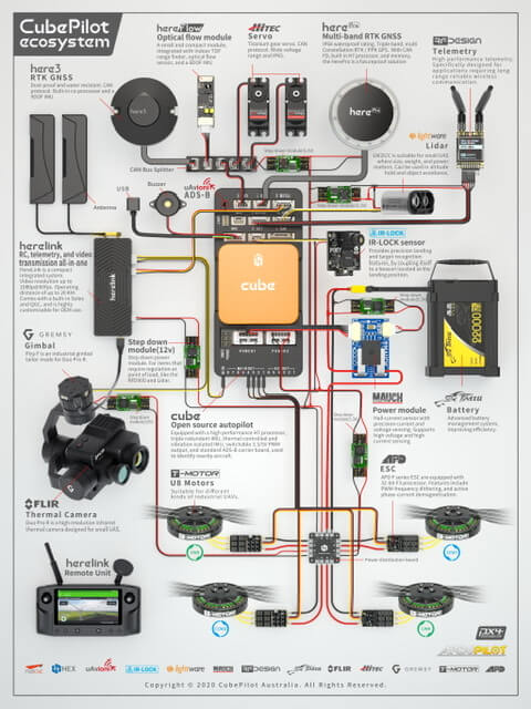
Pixhawk2 (Cube Black) is a well-supported platform by Ardupilot. The “cube” is the insert to the breakout module with various connector interfaces. The entire module is less than 4″ long by 2″ wide. This will mount within our copter frame. At the time of this writing Pixhawk4 is available.
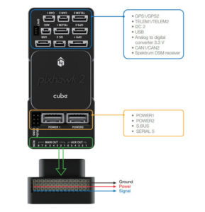
The, “Pixhawk” is generally the interface module for a, “cube” (orange below) that contains the inertial and other sensors package together with the microprocessor. The module supports cable connectors to various sensor, media, and communications peripherals.
Flight Controller Software
Ardupilot, “Copter” is our code platform starting point. I chose to go native Linux for my development environment as I have a laptop running Ubuntu. The Ardupilot tool set-up instructions cover Mac and Windows, but I went the straight Linux route. In my experience it’s easiest that way for projects like this, as the Windows environment tools can be a bit of a pain requiring VMs and such. I didn’t study Ardupilot Windows set-up in-detail so maybe it’s not a problem. In any case, just know that in what follows I’ll be giving you the Linux tool suite details.
Ground Station
Mission Planner
OK I lied, I’m using my Windows machine to run MissionPlanner from Ardupilot. Once we get set-up we’re able to use this tool to hook directly to our cube above via USB or telemetry radio. It fairly short-order we get to a point where we’re loading our own builds and able to see live sensor data in Mission Planner from the above hardware sitting on our bench.
Telemetry
When you first get going on the Ardupilot build-load cycle you can use a USB cable from your development machine to the Cube. Soon after, either for convenience on the bench or definitely when you need to fly you’ll need a radio link.
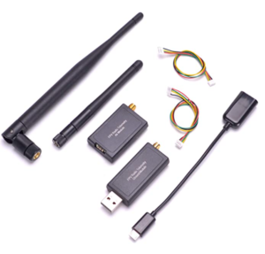
I chose the 900MHz radios below (approved in US, most other places you’ll need to go 450Mhz). They’re plug-and-play between “Telemetry 1” connector on the PixHawk module above and a USB serial port on the Mission Planner PC. I’m able to connect at 57600 Baud with these radios (set 57600 on the PC side and it will just, work. If 115200 works for you that’s great).
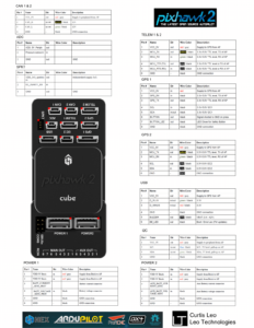
I had to hack the cables that came with the radios I bought because the connector does not match the mating connector on the PixHawk. I used the pinout description for the PixHawk2 above and this APM radio reference pinout below to figure how to wire my 4-wire radio interface to a hacked cable into the PixHawk. This board here has nothing to do with our design. I just used this picture for the, “Radio Tel” description.
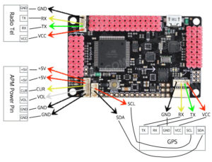
My hack worked. I Recommend you find a radio that has the proper cable end for a PixHawk2. There are many APM2.6 and higher Telemetry Radio options available through Amazon or other outlets. I didn’t notice the connector issue until I received my radios, so dig a little and you can avoid my hack.
Quadrotor Platform
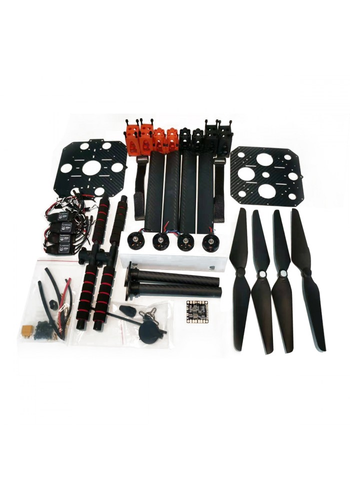
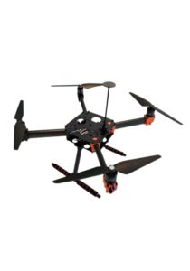
I picked a platform well-built for the PixHawk2, the EDU-450 Drone Kit. I purchased it here. It includes the motor electronic speed controllers (ESCs), 880 Kv motors.
Simulation Environment
Ardupilot SITL
The Arudupilot codebase includes a software in-the-loop (SITL) simulation environment. This permits the flight controller outputs to actuate a software model of a quadcopter, which then feeds-back sensor inputs to the flight controller software. Implementation of the physics model and simulation can be accomplished a number of ways. There appear to be a handful of 3D graphics rendering simulation environments.
Real Flight and FightGear
RealFlight and FlightGear appear to offer quality 3D graphical simulation. This looks good for presentation-quality simulation. I followed the Ardupilot SITL guide to get FlightGear going, but I’m more comfortable with Matlab for coding details of our quadcopter mechanical model, introducing disturbances and other aspects that will test the robustness of our designs.
I’m less interested in the graphics of the simulation than the performance details so I’ll be using the Matlab simulation environment through Ardupilot SITL.
Matlab
Ardupilot SITLs JSON simulation option permits SITL to output data to Mathsoft’s Matlab or Simulink. Consider a modest investment in Mathsoft’s home-use license if you’re interested in this approach. Specifically, I’ll be using SITL’s Matlab option. Follow the link to a quality demonstration video.
This is the basic idea:
- SITL runs the control loop on the flight controller simulation machine
- SITL connects to a Matlab instance on same or other computer via specified IP
- The Fligth Controller output’s platform state information like altitude as well as roto command outputs via the JSON payload.
- The Matlab server processes these data through a mechanical model of the platform.
- The rotor commands through this model result in updates to roll, pitch, yaw, and altitude.
- These modeled state outputs from the simulated, “real platform” feed back to SITL via the JSON response to the flight controller.
- The Flight Controller processes these changes as sensor inputs.
This process repeats at a sampling rate. In this manner we can modify and test our real-time control code.
We can also change our physics model. Perhaps we degrade performance of a motor or propeller, introduce wind, or other disturbances. This, “real world” situational simulation will be done through modifications and enhancements of the Matlab code used to model an actual platform.
We will then be able to test the robustness of the controller code and make enhancements as needed. We’ll iterate considerably in this environment before we attempt to fly our design.
Stationary Test Stand
I’ll be adding an entirely new Ardupilot attitude controller to implement the Linear Quadratic methods. I’ll do a lot of work on the bench with software simulators. Then I’ll graduate to real hardware, but to prevent crashing around and to permit controlled experiment analysis of the attitude control methods I’ll want a stationary test stand.
A company called MINDS-i education markets a gimbal rig demonstrated in the following video. This is exactly what I need, but this would be both too small for my rig and also too expensive for me, especially because I can build one in my shop!
I’ll do a separate post covering the construction of my gimbal test stand. For now, the MINDS-i demo video illustrates the 3 rotational degrees of freedom (roll, pitch, yaw) it will allow. It prevents the 3 translational (X,Y,Z) degrees of freedom that would crash it all over the shop as I work to refine the control schemes!
What Next?
Upcoming posts will jump around between Ardupilot coding of the Linear Quadratic attitude controller, test stand build, bench software-only simulations, and any topics the implantation phase floats to the surface.
We’re finally going to get busy building and realizing the math and the methods!