Maximum Thrust vs. Battery Voltage
[latexpage]
In a previous post we got the Ardupilot simulator stable running the linear-quadratic attitude controller, but we had a hack in-place for normalizing our body torque commands from Newton-meters to -1 to +1 for input to the Ardupilot motor sub-system.
Purpose
This post uses a test stand to measure maximum available thrust over a range of supply (battery) voltages in order to gain a normalizing constant we need for the output commands of our linear quadratic controller. With normalized commands we drive -1 to +1 commands into native Ardupilot motor code which in-turn drives PWM outputs to electronic speed controllers (ESCs).
Equipment
After all the modelling and equation solving for the motor-prop assembly in previous posts I’ve been wanting to take some measurements. I found a reasonably priced test stand from Tyto Robotics: their model 1520. I purchased the add-on optical speed sensor. All-in with shipping was near $200.
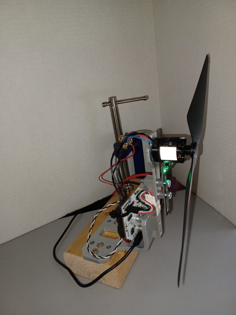
Here’s the 1520 on my bench with the AIR2216/880Kv motor and T1045 prop that comes with the Hexsoon EDU-450 kit. On my setup here you can see a green LED on the RPM sensor board as well as the reflective tape on the motor rotor.
Problem
In the Linear-Quadratic controller implementation within the Ardupilot Attitude Controller we’re calculating roll, pitch, yaw command outputs as Torques. Challenge is, Ardupilot motor code desires normalized roll, pitch, and yaw commands scaled -1 to +1.
Focusing on a single axis, say roll, once we have a roll torque to command on each iteration we need to cram a normalized roll (-1 to +1) into the Ardupilot motors object. From there it will result in PWM output to electronic speed controllers (ESCs) to drive the motors.
Roll torque is differential thrust from a cross-body pair of propellers multiplied by the arm length. If we divide our controllers command torque by arm length we get this differential thrust command but…
How to normalize it for the Ardupilot motors and PWM stack of code?
- We need a maximum thrust
- with added twist that it’s voltage-dependent as battery voltage drops during flight.
Solution
Characterize the motor-prop assembly maximum thrust as a function of battery voltage. Call it, Thrustmax.
Given Thrustmax and also run-time battery voltage sampled in real-time, scale Thrustmax down to a Thrustavailable.
Then at run-time we’ll normalize that differential thrust for roll and pitch with a divide-by Thrustavailable (first clamping the differential command to +/- Thrustavailable ). This will give us a normalized -1 to +1 roll and pitch to command the resident motors object in Ardupilot.
Yaw is different as it’s driven by propeller drag force and resultant moment induced about the craft’s center. We’ll look at that later.
Max thrust derating by battery voltage
The first plot below illustrates what to expect for thrust as our Lithium Polymer (LiPo) battery voltage drops during flight. A single LiPo charged cell is nominally 3.7 volts to 4.2V. We’ll likely use a ‘4S’ configuration (4 cells in series) for nearly 15 Volts at max charge.
I don’t yet know what a low voltage cuttoff will be. I read maybe 3.2V per cell which means our minimum operating voltage might be say 10-12V. In any case I tested with my bench supply as follows in order to produce data seen here.
Procedure
- Set bench supply at 15V.
- This is source voltage to the ESC driving the motor on the test stand shown above.
- Step ESC from 1000 to 2100 with intervals of 100.
- This results in a 1-2ms pulse to the ESC in 100 microsecond steps.
- Hold each step.
- Sample motor speed and torque mid-step.
- When the step’s steady-state is established.
- On pause after last step.
- lower battery voltage.
- Jump to step 2 above.
Measured Thrust over ESC range by Battery Voltage
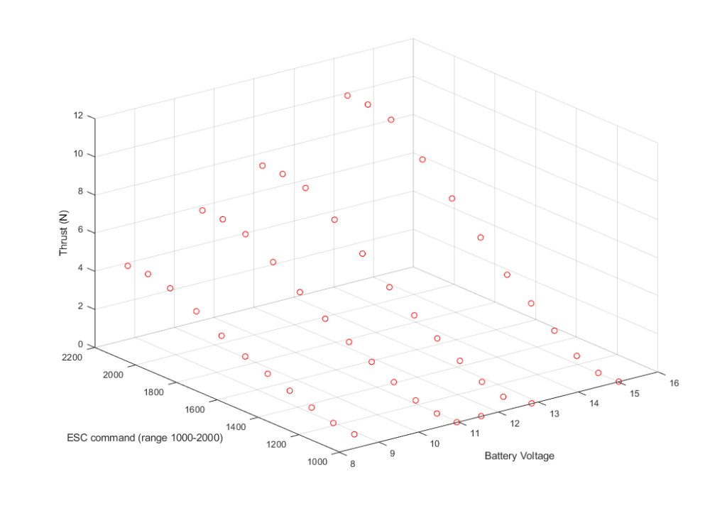
We’ll get our data off the 2-D plot below. These 3-axis plots illustrate the test runs and reveal the relationship between battery voltage, ESC command, and measured motor speed and torque.
plot: Thrust output by ESC command input over range of Battery voltage.
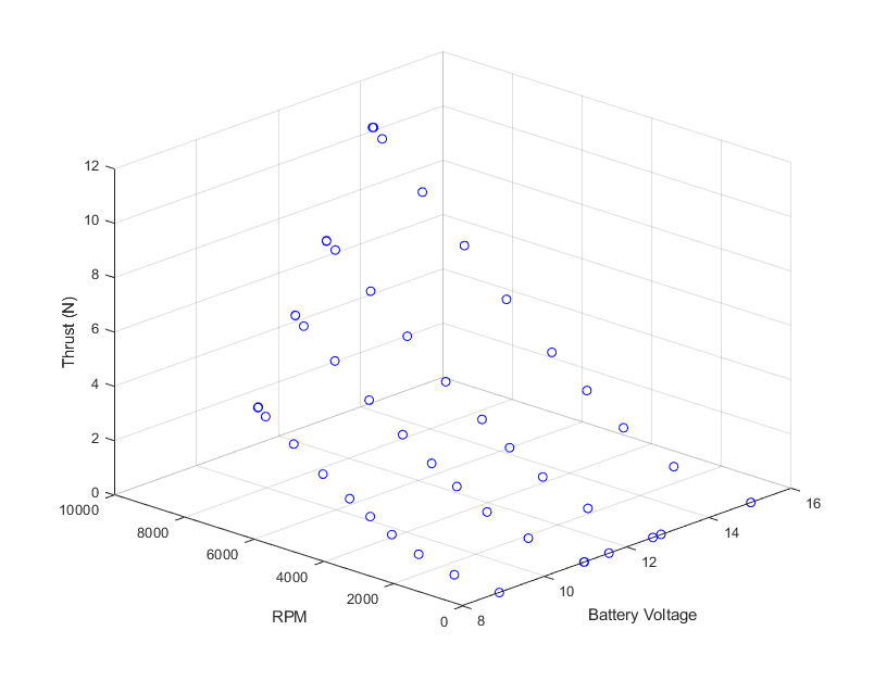
Thrust derates with voltage because the maximum RPM drops with voltage. You can see this in the following plot where we’re plotting against measured RPM instead of command. We don’t actually drive thrust, we drive motor speed, which in turn provides thrust proportional to RPM squared as described in an earlier post.
In the perspective view here you can see it’s actually RPM that is dropping with lower voltage, and consequently thrust. Thrust it our output of interest though.
plot: Thrust output vs RPM output from ESC command over range of Battery voltage.
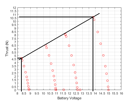
What we care about is the maximum thrust possible as a function of battery voltage. Note from the plot below how no-load battery voltage droops up to max thrust (RPM) for each step. Let’s take our voltage difference from the loaded maximum drive output for the first and last step. We’ll take the thrust difference and get our slope. It’s nicely linear.
\begin{equation}
\Delta V = 13.75 – 8.25 = 5.5V
\end{equation}
\begin{equation}
\Delta Thrust = 10.5 – 4.5 = 6N
\end{equation}
\begin{equation}
m = \dfrac {\Delta Thrust}{\Delta V} =\dfrac{6N}{5.5V}\approx 1\dfrac{N}{V}
\end{equation}
Plot: Maximum Thrust at Battery Voltage
Run-time equation for our normalizing value: Thrustavailable
The equation here will replace the normalization constants described in an earlier diagram. Our interest then was to get stable with the simulator, so we hacked-in a scheme. Here we’ll have an acurate divisor for the -1 to +1 motors input range.
\begin{equation}
Thrust_{available} = Thrust_{cal} + m\cdot(V_{batt,current} – V_{batt,cal})
\end{equation}
Conclusion
We’ll confirm these results with a battery stack instead of a bench supply to finalize our numbers, but it looks like we have a tidy linear derating to apply here. We’ll calibrate somewhere near a fully-charged battery pack voltage and store these two parameters for Ardupilot:
- Thrustcal (Newtons)
- ThrustVcal (Volts)
- ThrustSlope (Newtons per Volt)
- This is unity above but we’ll store it anyway
The above run-time equation and application of these parameters will cover cases where run-time voltage is higher than the calibration voltage.