Quadrotor: 4 props to stabilize the platform6 min read
In the last post we arrived at a mathematical model for the combination brushless DC motor (BLDC), gearbox, and propeller model. A small quadrotor motor will not have a gearbox. It will have the propeller mounted directly to the shaft of a small hobby motor. In larger craft a gearbox helps match the motor to the load: the propeller.
Here we’re taking a detour to appreciate the point of the motor: drive a propeller to produce thrust
Table of Contents
Propeller Thrust
The speed of a propeller affects the exit velocity of the air behind it. The force the propeller offers in the forward direction is related to this fast moving air leaving the prop compared to the air in front of the prop. NASA has some great resources online. You can read about simple propeller dynamics here, where this image was copied from:
Jumping to conclusions, these equations tell us that the thrust (force) offered by the propeller is proportional to the difference between the squared air-speeds across the propeller disk. The NASA link explains this is a simplified model.
Parameters of Thrust
In the above equation for Force (in red) you can see that multiplier, “.5ρA”. That is the proportionality constant that multiplies the squared air velocity difference to give us a force estimate. Propeller area is A (your basic area of a circle). The 0.5 comes from the dynamic pressure equation in white at the bottom of the black box above, and as the force equation is derived it flows through to the force equation.
The symbol ρ (rho) is the air density. It’s not constant. As an aircraft moves higher the density decreases, and as it moves through air of different temperatures the density changes. This is a simple model though, and our quad-rotor is not going to experience drastic air density changes such that the system could actually fail.
This is a design consideration though: what are the limits of a system? For example, how high in altitude, into rarefied air (thin, not dense) could a propeller craft travel? At some point we simply could not produce enough force. Would a propeller get us very far in the thin air of Mars? We’d need a larger diameter for sure.
Feedback Control
Back to earth, we are now going to get to the neat part of feedback control: it let’s us get away with relatively simple physical models like the image above so long as we understand their limits and basic operation. We can be content with roughly knowing the proportionality constant above because we are going to use sensors on the quadrotor to feedback tilts and position errors relative to where we want the platform to be.
Through some math these errors will compute to commands for the 4 motors (armature voltage changes for each motor). These voltage changes will change the motor speeds. these speed changes will alter the squared-velocity terms in the above propeller force equations for the 4 propellers on the quadrotor. We don’t need to know the above equation precisely. In fact, the actual system will exhibit, “non-modeled dynamics” including, “non-linearities”: complicated physical phenomenon we don’t have clean-and-easy math for.
Instead, we basically ask for more-or-less motor speed many times per second on each of the four motors to keep it level, or to twist, or tip-and-move in one direction. We’re asking for relatively more-or-less, so we don’t need to be absolutely certain of all the parameters and values that govern the movement.
There are things we can do wrong to make the commands oscillate and send the quad-rotor out-of-control. If we design our feedback control loops correctly we can guard against this.
This is all happening many times per second: sensors feeding-back to math that knows where we want to be, and more math to calculate individual motor commands based on the difference of where we are in the sky (and how we are tipped, tilted, or rotated) relative to where we would like to be, how level we want to be, and which direction we want our quadrotor to be facing. The, “math” will be simple arithmetic in a small computer on the quadrotor.
Propeller Speed Differential Equation
Remember the post with the dynamic model for the motor+gearbox+propeller? We ended-up with this differential equation for propeller speed:
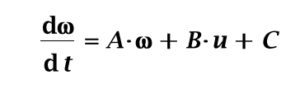
Recall, “A” and, “C” are themselves functions of a nominal propeller speed, so the above equation is intended to apply around a certain propeller speed. The farther from that speed we drive the propeller by assuming pre-computed constant, “A” and, “C” the less reliable this equation will be. This means any controller we design on paper after assuming a nominal operating speed for the propellers could become invalid and cause our speed control to fail and the quadrotor to go out-of-control. We’ll need to determine how sensitive we are to this. If we need to worry about it we will modify our entire controller over the speed range.
We’ll think about this later. For now, the equation above appears below in block-diagram form. Notice the integrator on the right. When we implement this it will be as a, “difference equation” resulting from a Z-transform representation of what will be a sampled-data (computer controlled) system. For now I show the classic integrator there because you can see how the diagram implements the above equation.
We add a speed sensor block. You can see a reference input that will come from the main quadrotor flight controller: the amount of speed it wants out of the individual motor represented here. Again, this will be more-or-less speed error calculated many times per second. We need to design a, “compensator” that will produce armature voltage commands (“u”) based on the speed error; namely, the difference between the reference speed and what the prop speed sensor is telling us.
There will be four of these, “loops” running independently: one for each propeller on the quadrotor. The main flight controller will be supplying each with it’s own reference speed many times per second.
Looking Ahead
Let’s end this post here. I started considering units and estimates for the parameters in the above equation (the A, B, and C terms) but getting into these details will be a good follow-up to this introductory post on the topic of controlling the motor speeds.
Also, this might become irrelevant to our build given encapsulated, “electronic speed controllers” (ESCs) available to drive our quad motors. In any case, if we were looking at speed control directly we’d go at it as shown in the following diagram.

