Quad-Rotor Control Design Series4 min read
What is a “quad-rotor”? Well you probably know it’s a thing with four rotors. We buy it as a, “drone” and we fly it with a remote control or via a phone app acting like one. I’ll probably bounce between the terms quad-rotor and quadcopter throughout. I mean the same thing. It is incredible what we can buy today for fun, and not too much money. Camera technology is awesome too.
I chose this gadget for a deep-dive because these things are popular. We can all remember seeing one fly, or maybe you own one. A quad-rotor is also a great example of a multi-output control system with multiple sensor inputs as feedback (MIMO system). We can go from simple to very complicated design ideas using this common vehicle as a platform for study.
How a Quad-Rotor Moves In the Sky
When you command a commercial quad-rotor drone to move up, down, right, or left relative to where it is in the sky, the machine processes that, “command” relative to the current location. Then it changes the speed of the propellers in such a way that the drone will move as you desire. A simple way of understanding it is as follows…
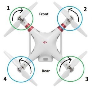
- Two pairs of Propellers, opposite each other on the two arms that intersect at the center.
- One pair rotates clockwise (CW – green above)
- The other pair counter-clockwise (CCW – blue above)
- Imagine driving one propeller of the green pair faster than the other green one.
- if we left the blue pair equal, the body of the quad-rotor will rotate about a line between the two blue propellers above.
- Same logic applies if we do the same to the blue pair, leaving the green equal: it will rotate about a line between the green propellers.
- If we vary each pair more-or-less simultaneously we create a more complicated tipping action of the platform, but it’s basically just doing as described above to create a, “virtual” axis of rotation
One last motion: Yaw…
- There’s one more less obvious motion: making the entire body we see above rotate about an axis coming out of the screen. This is, “Yaw” for this platform.
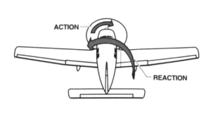
- This relies on the counter-acting torque on the body of the quad-rotor as a result of the drive torque on the propellers: It’s Newton’s Third Law stating that for every action there is an equal and opposite reaction.
- Here’s a way to visualize it for a single propeller. The plane wants to rotate the opposite direction. For a single-engine craft like this, the ailerons and rudder work to cancel this out.
- The quad-rotor has four propellers. Here’s how we can make the quad-rotor, “spin” like a figure skater while remaining otherwise stationary
- let’s say we start in a fixed spot in the sky, level, and not moving: hovering still.
- If we speed-up the blue propellers above just a bit, and slow down the green just a bit so the total, “up” thrust is otherwise still the same…
- the little extra reaction torque on the body of the quad-rotor by the fast propellers compared to the slower propellers will cause it to spin one way.
- If we flip it around and make the green a bit faster, the quad-rotor will yaw the other way.
No matter what the current roll, pitch, or yaw angle is at a given moment, if we increase or decrease every motor drive torque by the same relative amount the entire machine will move along the vertical axis of the drone, in theory.
Complications…
There’s a lot going on relative to non-linear propeller drive force equations, wind, and gyroscopic effects perhaps. The above explanation is simple enough for understanding the basics, but we rely on sensors to continuously measure and feeedback to the body controller so it can update the propeller speed controllers. This occurs very many times per second.
The presentation below does a good job of introducing the sensor concepts, and covers much of what I will likely repeat, but I am going to go into some more detail in a few areas to cover how to derive some of the equations, how to simplify the model to the degree shown here, or maybe not simplify it.
Also, this presentation looks to cover the simplified modelling and control using Proportional-Integral-Derivative (PID) controller pairs that act independent of one another to control pairs of propellers relative to, “level” flight. That’s a fine and robust simplification for a stable camera-drone platform.
I’m interested in learning what it would take to control one of these things over severe bank angles, or a larger, “flight envelope” so this topic is going to take us into a lot of details and learning. Can’t wait to get into it!

