Propeller Blade, “Lift”15 min read
In the last quadcopter post we clarified the load torque of the propeller applied through the gearbox to the motor shaft. We won’t even have a gearbox but the terms in the equation needed clarification. We haven’t yet covered the main point of the propeller: LIFT! A propeller blade is just a spinning wing at each cross-sectional location.
The propeller force described in the NASA diagram in an earlier post summarizes the propeller-induced thrust force but it doesn’t tell us anything about the fluid mechanics around the prop blades.
Table of Contents
Wings and Lift
Motivation
My MIT Fluid Mechanics professor Ain Sonin would not be happy with me if I didn’t remember a very compelling demonstration he performed to illustrate, “streamline curvature” as the lift producer. The link on his name honors his passing in 2010. He died at a young age of 72. I vividly recall his interesting lectures, impeccable sketches, approximation techniques, and his evident love of teaching. Thinking of what I learned from him, and what I should have better absorbed then, I want to cover lift here.
Propeller as Airfoil
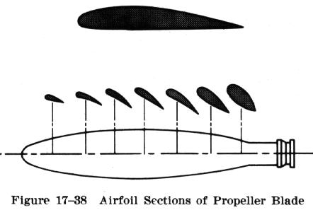
Previously, we considered the torque load as the drag on the motor. It makes sense that if we spin a propeller shaped like the example below the blunt nose and general form of the propeller requires some torque to spin it through the air. This is the drag you feel on your hand when you stick it out of your car window.
Let’s stick with the hand-out-the-window example. Whether we are actual kids or big kids, we all sometimes put our hand out the car window with our palm down. Then we tip our hand just a bit back and it feels like it wants to go up. Is this how a wing or a propeller (a spinning wing) creates sustained lift? No!
A titled hand can rise with the force of air outside the car window but we cannot sustain flight (level-flight) or produce along-axis force from spinning a propeller unless the blades produce, “streamline curvature”! This is something hard to do with your hand out the car window unless you have a very unique shape to your hand and the angles are just right.
You are likely not producing, “lift” with your hand. you are just feeling the drag on an angle and that wants to push your hand up-and-back. If it weren’t attached to your arm it would just flip backwards. If an airplane wing attempted to climb by tipping itself backwards the plane would flip back like a mattress on top of a minivan going down the highway.
It’s about, “Streamline curvature” over the top surface
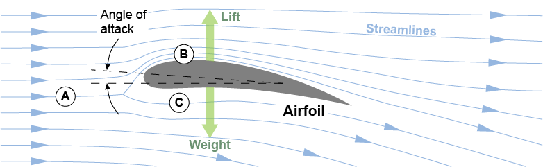
So what is really going on? In Professor Sonin’s class we were introduced to the fundamentals of Euler’s Equation, and its application in cylindrical coordinates along a, “streamline”. Streamlines are the blue lines flowing around the cross-section of a wing below. Bernoulli’s equation is what we learn to apply in basic fluid mechanics. It can be integrated from Euler’s equation. It’s handy for very many engineering problems, but Euler’s gives us a deeper level of understanding.
If you look at the cross-sections of the propeller above you can see they look like a bunch of wing cross-sections. The propeller is just a spinning wing. At any moment in time any of those propeller cross-sections above has streamlines flowing overand under similar to the simple wing diagram below. As it spins, part of the torque supplied by the motor goes into forcing these streamlines to curve around the blade. It is the nature of this curvature that gives us this, “lift” force, which we call thrust for the propeller.
For a wing, the, “weight” in the diagram is the weight of the entire plane, so the wings must produce lift to counter-act that weight, and extra lift to accelerate that weight upwards: to climb. When our propeller spins, we want it to pull a plane forward or a helicopter up (quad-copter in our case). A prop-driven airplane creates lift at the propellers to produce flight speed necessary to produce vertical lift by the wings! The prop, pulls the plane forward with, “lift” from the propellers and the plane stays aloft through, “lift” at the wings. the same principle is applied in two directions!
Our quadcopter will hover when the total lift from the four propellers matches the total weight. It will accelerate upwards or laterally when the total lift exceeds the total weight. The force we get out of a wing and a propeller is due to something you can see in the graphic above: the “streamlines” on the top (B) (the top surface of our quadrotor propellers) have more curvature than the streamlines on the bottom (C).
Euler’s Equation
The James A. Fat textbook below was in paper draft for Professor Sonin’s course at MIT 25 years ago now. Preparing for this post motivated me to (re)learn this material, so I just bought a bound copy of Fay’s book for my shelf.
Recommended Reading
We’ll gloss over considerable detail but fill a couple of gaps in the derivations that get us to, “streamline coordinates”. Otherwise, this post is just organizing references in hopes of creating a useful guide on this topic of lift as a result of, “streamline curvature”.
I can’t improve the theory relative to these expert sources. I cannot come close to the genius of Euler and the father-son Bernoulli team! I hope I can clarify it for we mere mortals.
Euler’s Equations
Euler’s Equations for inviscid flow will reveal what causes the lift once we get it into the right form. Inviscid flow is ideal, simplified flow, assumed to slip past the wing with no surface interaction (no shear, so no boundary layer, eddies, turbulence)…only the shape of the wing affects the flow, not the surface characteristics.
The Equations will reveal where the  for the propeller speed-to-thrust relationship comes from. We glossed over this topic in the post with the NASA diagram where we saw the simplified equation with the term.
In the last post we resolved some confusion around the motor+gearbox+propeller model for load on the motor. We cover here the entire point of spinning the propeller: lift from the blades or aggregate thrust along the axis of the propeller.
The following PDF extracts key pages from Fay’s book (my old draft copy) that lead us to, “Euler’s Equation in Streamline Coordinates”. It includes a few pages of Bernoulli equation derivation. It is integrated from Euler’s equation along a streamline. It is a frequently applied formula.
The typically overlooked perpendicular-to-streamline (normal) Euler equation tells us about lift from an airfoil!
James A. Fay: Euler's Equation
Example Application
This tutorial by the late Professor Sonin is excellent. I enjoy his neat sketches and remember them well, as I took notes in his class and attempted to match his detail and neatness.
Sonin: StreamLine Equations of MotionIt’s not easy to digest the mathematical symbols, multivariable calculus, and terminology unless one has an excellent memory of their studies or practices these topics regularly. We’ll fill in some gaps below.
Cylindrical Coordinates
Although it might look daunting on its own, let’s accept Euler’s equation in cartesian (XYZ) coordinates. Then in Fay’s and Sonin’s material above we see we need cylindrical-streamline coordinates to get the equations of motion into some form that will enlighten us on this lift force we so desire.
Step-by-Step Derivation
The key to deriving cylindrical coordinates is to start by representing the unit vectors relative to a Cartesian system.
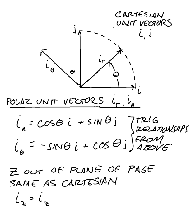
We start with radial and angular unit vectors in an X-Y plane, and we know Z in the Cartesian system is the same as Z in Cylindrical, so from the above diagram…
(1) 
(2) 
(3) 
A big difference between cylindrical coordinates and Cartesian coordinates is the rotation of the ‘r’ and ‘ ‘ axes in time, as our, “fluid particle” moves in . Hence showing as a function of time in the above equation.
We need derivatives of the unit vectors, and here’s what they are:
(4) 
Look at the trig in parenthesis. It’s our term for  above so…
(5) 
And
(6) 
Again we see a familiar expression from above so this simplifies to…
(7) 
It is these moving axes that give us what look like extra terms in the cylindrical equations of motion. We get to them simply by taking derivatives of position and velocity.
We start with the position of a particle in cylindrical coordinates.
(8) 
By chain rule, we differentiate position to velocity as…
(9) 
But we have terms for the derivatives of the unit vectors from above, and  so velocity simplifies to…
(10) 
Then we differentiate Velocity to get acceleration, again by the chain rule…
(11) 
and we again replace those unit vector derivative terms and to get, with a bit of rearrangement…
(12) 
The  is the, “Coriolis” acceleration term and the
  is the “centrifugal” acceleration term for a particle. They’re nothing more than a manifestation of the rotating unit vector
  , which we can see by following the derivation above from cartesian to polar.
Streamline Coordinates
These are just a slight twist on Cylindrical coordinates. We relate cylindrical coordinates to streamline coordinates as follows…
 The perpendicular-to-streamline or, “normal” to flow unit vector.
 The along-path unit vector, tangent to streamline unit vector.
 By right-hand-rule, normal to the above two unit vectors: The, “up” axis of a cylindrical system. Out-of-page axis here. No fluid dynamics along this axis.
The derivative relationships are

That last denominator might look confusing but it’s just as simple as spanning a distance  with angular change
  operating on a radius
  .
.
If you now go back to the Fay PDF and accept Euler’s Equation in Cartesian coordinates on page 90-91 in the PDF above you can use the steps above to get confident with the cylindrical acceleration representation, also on page 90. From there you use the unit vector reltionships to adjust the cylindrical representation to the streamline representation and you get to Fay’s page 105 here below.
Understanding, “lift” from Streamline Coordinates
The key equation for us is
(13) 
V and R being likely functions of n, integrating to estimate a pressure difference would be non-trivial. Sonin’s paper gives us a chance to solve the n-direction equation with models for Velocity and streamline radius as a function of n. See the paper to attempt this derivation for flow over a simple hill.
Fay and Sonin state that this is not a practical method for calculating a lift force. It is over-simplified, and we seldom have representations for V and R as a function of n over a range of s-vectors tangent to the flow over a wing. If we did, we’d still need to integrate them. However, this treatment tunes us into the physics of the problem. Our goal here is physical understanding, even if exact solutions elude us.
The approximation below from some 1995 Sonin lecture notes shows us what we need to know to appreciate why our prop-speed-squared ( ) is our lift producer.
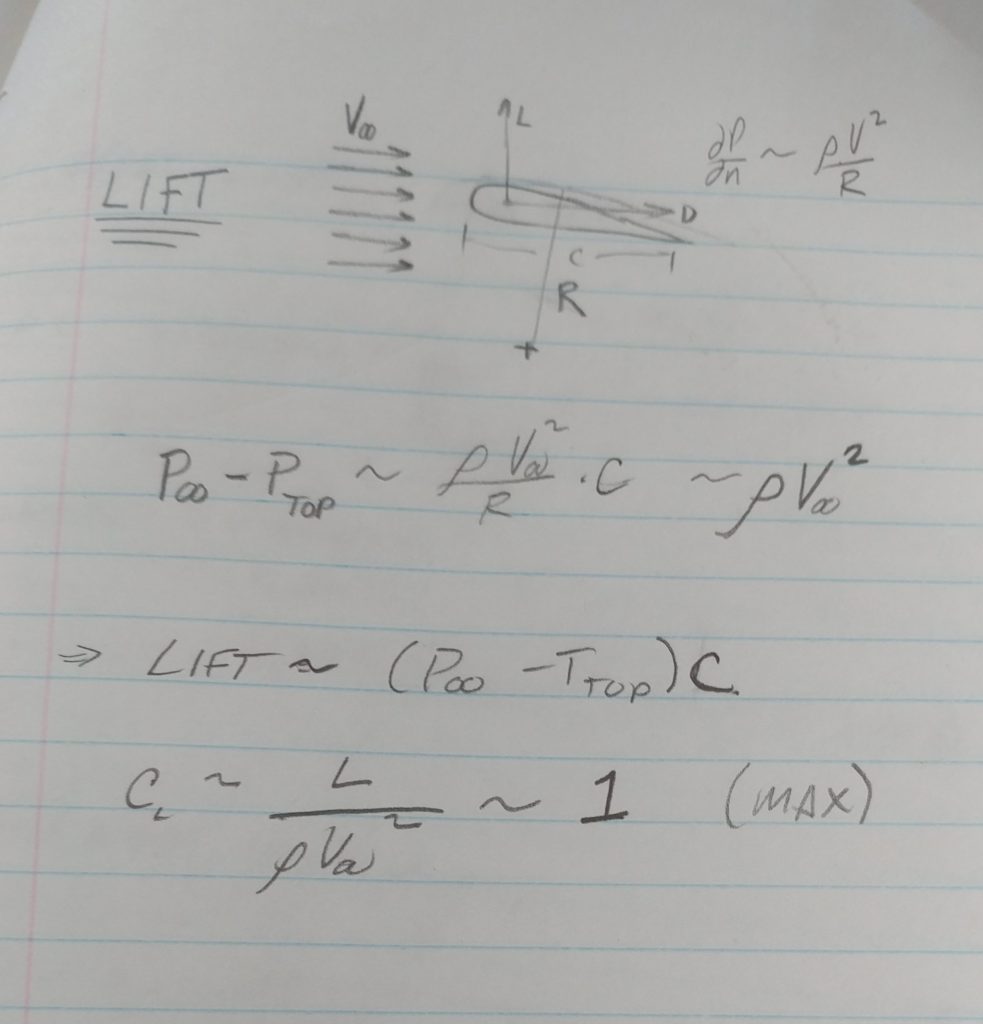
Understanding Approximations for Lift
The n-direction equation tells us what we need to know to understand the lift generated by airfoils (thrust from propellers: spinning airfoils). As Sonin’s paper above states, “The n-direction equation states that when there is flow and the streamlines curve, the sum  (which is constant when the fluid is static) increases in the n-direction, that is, as one moves away from the local center of curvature.”
If we imagine integrating from the wing’s surface to far above the wing the streamlines way out at our approximated infinity would have a very large radius while the airspeed is  .
.
If we just assume airspeed is everywhere (a crude approximation because we are speeding it up over the wing) but let the streamline radius get larger from top-surface radius R as we move away from the wing then we can estimate a low pressure on the top of the wing proportional to  as indicated in the lecture notes above.
Remember that if our propeller is spinning with angular velocity  . At any point along the propeller where we could take a cross-section to sketch an airfoil diagram the “V” is just the propeller rotational rate times the radius from the propeller axis to the location of our cross-section.
(14) 
At this particular propeller cross-section, we could estimate the free-stream velocity-squared as
(15) 
There’s our propeller term!
We now see how propeller rotational speed squared () is the variable responsible for, the “lift” generated by a propeller blade. It is proportional to a simplified, assumed freestream velocity at any point along the blade where we take a cross-section as above. This is a highly simplified model, but it gets us to the essence of a propeller as an airfoil.
Observe this on your next flight
Next time you land or take off in an airplane observe the flaps that extend down from the leading edge and back from the rear of the wings. They create a shorter wing curvature radius and a larger wing surface. This increases lift.
It is required because the plane is going much slower at take-off and landing than when cruising so the pressure difference across the same wing would be less at low speed.
So, the modifiable airfoil extends the flaps, creates a larger surface over which the pressure difference acts, and adds more curvature to increase the pressure difference at low airspeed. This occurs at the expense of drag, however. Given that it is only needed at low speeds, the flaps are retracted for cruising, where  is higher, so we don’t need the curvature and extra area the flaps provide.
There remains that  term for air density, and we know it is higher in the troposphere down near the ground than up at 30,000 feet and higher. We’re going to ignore this because our quadrotor is going to operate near the ground. Planes are more sensitive to “stall” (failure of the lift from wings) at high altitudes due to the rarefied (low-density) air. Airspeed and angle-of-attack are critical factors up there.
Conclusion
We now know that when our quad-rotor main controller asks our 4 motors for more-or-less speed many times per second it is the speed-squared () that gives us lift!
I hope the references above and any gap-filling explanations help convey the, “lift” phenomenon!


2 Replies to “Propeller Blade, “Lift”15 min read”
Thanks for the great overview and trip down memory lane… Took me about two hours to follow Fay’s mathematical gymnastics using Euler’s equations, but finally after referencing the calculus refresher I stole from your office I was able to get it right. Great job of describing the derivation of velocity and acceleration using the cylindrical coordinate system. The cylindrical coordinate system seems much more intuitive in describing fluid systems.
Thanks! I’m glad this got you into the ol’ math! Indeed for the “curved” streamlines cylindrical coordinates make the “lift” phenomenon easier to see.